Project Overview
This project is the engineering of a ventilation system for a Train Painting Booth — a 33m(L) × 6m(W) × 6.5m(H) facility designed to manually paint LRV (Light Rail Vehicle) car bodies, with train sets up to 28 meters long (2 car bodies). The engineering challenge wasn't just building an enclosure, but managing three distinct airflows (fresh air, hot air, exhaust air) in balance across that large enclosed volume, while maintaining paint quality and operator safety.
Client requirements included a one-way painting process (train pushed in and pulled out by shunter), use of a high-pressure electrostatic aircoat system, and compliance with safe working conditions in a potentially hazardous area. The system objective was one integrated ventilation chain — not standalone HVAC components.
Client Challenges
High-temperature control for paint curing (up to 150°C design)
Paint overspray and air contamination from a high-pressure electrostatic system
Uniform airflow across a 33-meter-long booth
Operator safety in a high-static-risk work area (electrostatic spray)
Environmental compliance — exhaust air must pass layered filtration before release
Maintenance accessibility across a large, multi-subsystem installation
Engineering Assessment
SRT's team conducted a site assessment (booth positioned outside the main shop building), a process study (one-way painting direction, electrostatic aircoat system characteristics), airflow analysis (balancing fresh air supply, hot air circulation, and exhaust across the booth's volume), equipment layout review (AHU room, heating box, and filtering chambers positioned around the booth), utility review (water circulation, compressed air for spray guns, and total system electrical load), maintenance accessibility (access doors, inspection points), and structural consideration (steel beam structure for the AHU room, insulated chamber construction).
Engineering Solution
Fresh Air Supply
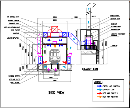
Fresh air is supplied through a single Air Handling Unit (AHU) sized 8×3.5×3.5m with a steel-beam support structure. Air passes through three filtration stages: a pre-filter SUS wire mesh (insect prevention), a second-stage EU-3 fixed envelope bag filter, and a third-stage EU-5 fixed envelope bag filter — reaching 95% filtration efficiency. A centrifugal supply fan rated at 180,000 m³/hr is driven by a 55kW high-efficiency motor (IP54), with air pressure monitored via a Magnehelic-type differential pressure gauge.
Hot Air Supply
Hot air for the paint curing process is supplied from a batch-oven type heating box (3.6×2×3m), constructed of galvanized plate with rock wool insulation (density 80) between the inner and outer walls. The heat source is a fine heater rated at 180kW. Design temperature is set at 150°C with an operating temperature of 120°C — explicitly noted in the engineering documentation as a value requiring reconfirmation against the actual paint specification, reflecting evidence-based engineering discipline rather than assumption.
Hot air circulation is driven by a centrifugal fan rated at 2,500 m³/min with a 20kW motor (IP54), distributed through 1,800×1,000mm galvanized ducting at a design velocity of 1-3 m/s.
Hot Air Return
The hot air return path brings air from inside the booth back to the heating box for reheating, rather than discharging the entire heated air volume each cycle — an approach that reduces heating energy load compared to a once-through system.
Exhaust Air System
The exhaust system uses a fan rated at 55kW, distributed through 1,800×1,000mm galvanized ducting. Before release to atmosphere, exhaust air passes through a silencer and an acoustic absorbent chamber for noise control, consistent with the layered filtration (water spray elimination + air scrubber) on the booth's filtering chamber side.
Airflow Control
Volume dampers and manual dampers are placed along the fresh air and exhaust paths to balance air distribution across three distinct zones of the 33-meter booth — rather than relying on a single supply/exhaust point for a space that large.
Noise Reduction
A silencer and acoustic absorbent chamber are installed on the exhaust path, with the AHU's own chamber using glass wool insulation over 1.5mm galvanized construction — acoustic treatment applied at two separate points, not just a single muffler at the end of the system.
Utility Integration
A water circulation system (2 pump units at 180 m³/hr, 22kW) supports overspray elimination at the filtering chamber. The system's overall electrical load is calculated and explicitly documented — total connected power of approximately 405kW, with a 20% safety margin bringing the design supply capacity to 450kW on the main 380V three-phase electrical supply.
Maintenance Access
Booth access includes an automatic weatherproof sliding door for primary access, plus two separate swing doors for personnel access — separating vehicle access from routine maintenance access. Check points along the exhaust ducting allow inspection without dismantling the entire duct run.
Engineering Design Highlights
Custom ventilation design for a 33m booth accommodating a 28m LRV
Airflow engineering — three airflows (fresh/hot/exhaust) balanced across zones
HVAC integration — AHU, heating box, and exhaust as one coordinated system
Acoustic engineering — silencer and acoustic absorbent chamber on the exhaust path
Multi-stage filtration — 95% efficiency via 3-stage air filtering + 2-stage water elimination
Structural support design — steel beam structure for the AHU room
Fabrication engineering — galvanized/mild steel construction across all chambers
Installation engineering — separated vehicle and personnel access paths
Commissioning support — covered within the technical specification package scope
Engineering Workflow
Technical Scope
| Scope | Demonstrated in This Project |
|---|---|
| Mechanical Engineering | Yes |
| HVAC Engineering | Yes |
| Industrial Ventilation | Yes |
| Fabrication | Represented in the specification package scope |
| Installation | Represented in the specification package scope |
| Testing | Represented in the specification package scope |
| Commissioning | Represented in the specification package scope |
| Documentation | Yes — technical specification and structured capacity calculation package |
Engineering Value Delivered
- Better, balanced airflow across a very large painting volume.
- Improved process quality via controlled, measured curing temperature.
- A stable, contamination-controlled painting environment.
- Lower contamination via 95%-efficiency, multi-stage filtration.
- Better operator safety via acoustic control and a system design that accounts for a static-risk work area.
- Reduced maintenance burden via inspection points and separated door access paths.
- Higher operational efficiency via high-efficiency motors and fans throughout the system.
Engineering Evidence
Engineering documentation supporting this project.