A high-speed flexographic printing machine, disabled by flood damage, was restored not only to operational status but to full production-speed reliability — through a structured engineering investigation that uncovered a hidden process interaction invisible to conventional repair.
Executive Summary. Following flood exposure, a high-speed flexographic printing machine at an industrial packaging facility required a structured engineering recovery to return to production. PT Sarana Rekayasa Tehnik (SRT) applied its Bottom-Up Engineering Recovery Cost Estimation (BURCE) methodology to assess damage at the component level, execute a targeted recovery program, and commission the machine back into service. During commissioning, the machine appeared fully functional — but SRT extended validation to actual production speed, revealing a printing register instability not present at lower speeds. Root cause investigation traced the issue to an interaction between the dust suppression system and material handling at high velocity — unrelated to the original flood damage. Engineering optimization resolved the instability, and the machine was validated at full production speed with stable print quality.
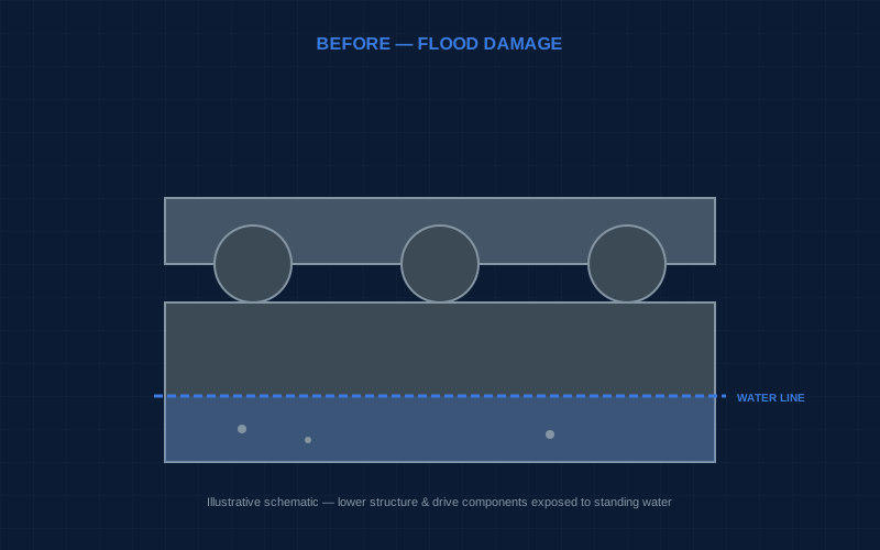
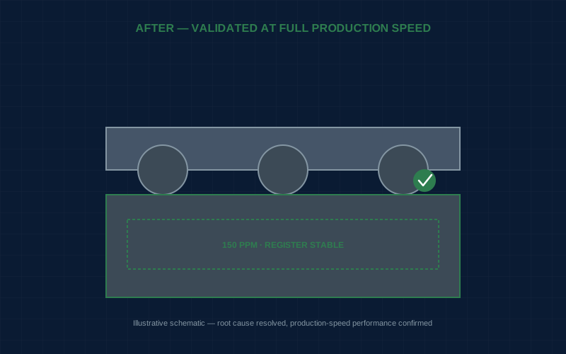
Drag to compare before and after recovery condition (illustrative)
Project Overview
The subject of this case study is a high-speed flexographic printing machine operated by a packaging manufacturer as part of a continuous, high-throughput production line. Flexographic printing machines of this class combine precision mechanical transport, servo-synchronized print cylinders, and integrated control systems to achieve consistent print registration at production speeds well beyond what manual or semi-automated equipment can sustain.
Following a flood event at the facility, the machine's lower structure, drive components, and portions of its electrical and control systems were exposed to standing water and residual moisture. As a production-critical asset, the machine's unavailability had a direct impact on the facility's output capacity, making a structured but efficient recovery program a priority for the asset owner.
Project objectives were defined as follows: conduct a component-level technical assessment to determine the actual extent of flood-related damage; develop a Recovery Cost Estimation based on verified engineering findings; execute mechanical and electrical restoration works; and commission the machine while validating that its performance — not merely its ability to operate — met the production requirements of a high-speed flexographic process.
Engineering scope encompassed technical assessment, Recovery Cost Estimation, mechanical restoration, electrical restoration, commissioning, performance validation, root cause analysis of an issue identified during commissioning, and subsequent engineering optimization.
The Engineering Challenge
Recovering a high-speed flexographic printing machine from flood exposure presents challenges that extend well beyond the typical scope of industrial equipment restoration.
Mechanical Precision. Flexographic printing depends on extremely tight mechanical tolerances between print cylinders, anilox rollers, impression cylinders, and the material transport path. Even minor dimensional shift can translate directly into visible print defects.
Servo Synchronization. Print stations are typically driven by independently controlled servo motors, synchronized electronically to maintain consistent print registration. Flood exposure to servo drives, encoders, or wiring introduces risk not only of outright failure but of degraded signal integrity that can manifest as subtle synchronization drift.
Printing Register Accuracy. Register accuracy — the precise alignment of successive print impressions — is often the single most sensitive performance indicator on a flexographic line, influenced by an interconnected set of variables: mechanical alignment, material tension, guide positioning, and, as this case demonstrates, factors not immediately obvious from design documentation.
High-Speed Production Requirements. A flexographic machine that performs acceptably at reduced or test speed does not necessarily perform acceptably at rated production speed. Dynamic effects scale nonlinearly with speed and frequently do not appear until a machine is tested under conditions that replicate actual production demand.
Integrated Control Systems. The mechanical, servo, and process control subsystems are tightly integrated. A recovery program that verifies each in isolation risks missing interaction effects that only emerge when the machine operates as a complete system.
For these reasons, the engineering challenge was not limited to repairing flood-affected components. Making the machine run is not, by itself, sufficient. A recovery program for equipment of this class must validate that production-level performance has been restored, under conditions that genuinely represent how the machine will be operated.
BURCE Engineering Assessment
SRT's technical assessment followed the Bottom-Up Engineering Recovery Cost Estimation (BURCE) methodology, in which recovery scope and cost are developed from verified component-level findings rather than a top-down assumption applied to the machine as a whole.
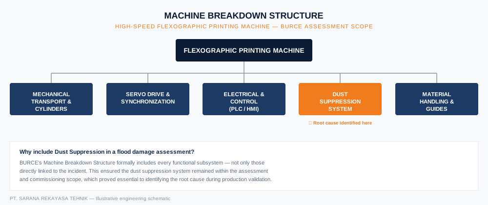
Figure 1 — Machine Breakdown Structure used for the BURCE assessment, covering five subsystems including dust suppression.
Machine Breakdown Structure. The printing machine was decomposed into its constituent systems: the mechanical transport and cylinder system, the servo drive and synchronization system, the electrical and control system (including the PLC and HMI), the dust suppression system, and the material handling and guide system. This structure ensured that every functional area — including auxiliary systems not immediately associated with printing performance — was included within the formal assessment scope.
Component-Level Assessment. Each component was inspected for evidence of flood exposure: standing water contact, moisture ingress into enclosures, corrosion initiation, and contamination of lubricated or precision-fitted assemblies. Electrical components were subjected to insulation resistance testing and continuity verification prior to any consideration of re-energization.
Damage Evaluation. Findings were classified by subsystem and severity, distinguishing components with direct water contact from those in elevated or enclosed locations that had escaped direct exposure — a distinction that determines whether a component requires full reconditioning, targeted verification, or no intervention at all.
Recovery Strategy. For each affected component, a recovery action was defined individually based on verified condition — from cleaning and drying, through electrical testing and selective replacement, to mechanical disassembly and reconditioning where contamination or corrosion risk was confirmed.
Engineering Decision Making. Every recovery decision was documented against its supporting technical evidence, ensuring the resulting recovery program was fully traceable and defensible to any technical stakeholder reviewing the project.
Recovery Execution
- Cleaning — Residue and contamination removed from mechanical assemblies, electrical enclosures, and the material transport path.
- Repair — Components with confirmed but recoverable damage disassembled, cleaned, and restored to design tolerance.
- Component Replacement — Components confirmed beyond serviceable limits replaced on an engineering-equivalent basis.
- Mechanical Alignment — Print cylinders, impression cylinders, and transport rollers realigned to design specification.
- Electrical Restoration — Servo wiring, control panel components, and sensor circuits repaired or replaced, with insulation resistance and continuity re-verified.
- Functional Testing — Mechanical drive, servo response, and control logic tested independently prior to integration.
- Servo Verification — Servo response, encoder feedback, and inter-axis synchronization verified against manufacturer specification.
- PLC Verification — Control logic, safety interlocks, and process parameters verified against original configuration.
- Commissioning — The machine brought into supervised operation, evaluated in stages from basic functionality to production-representative conditions.
Commissioning & Performance Validation
Initial commissioning confirmed that the machine was mechanically and electrically functional: all drive systems engaged correctly, the control system operated without fault, and the machine produced printed output under standard test conditions. On this basis, a conventional commissioning process might reasonably have concluded that the recovery was complete.
SRT's engineering approach treats initial functionality as necessary but not sufficient for project closure. Because the asset's operational purpose is high-speed production printing, commissioning was extended to a staged production trial at increasing line speed.
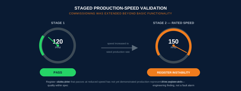
Figure 2 — Staged production-speed validation: register stability at 120 PPM, instability emerging only at rated speed (150 PPM).
Production Trial at 120 PPM. Printing quality met specification. Register accuracy, print consistency, and material tracking were all within acceptable tolerance.
Production Trial at 150 PPM — Rated Production Speed. At full rated speed, printing register drift became apparent, resulting in unstable print quality inconsistent with the machine's specified performance envelope.
This finding illustrates a principle often underweighted in equipment recovery generally: commissioning should validate process capability, not merely machine functionality. Had commissioning concluded at the 120 PPM stage, the machine would have been returned with a latent performance defect likely to surface during actual production — at a point where diagnosis is more disruptive and less structured.
Root Cause Analysis
The register instability observed at 150 PPM was not accompanied by any error condition, mechanical fault indication, or servo alarm — the control system reported normal operation throughout. This absence of a conventional fault signature meant the issue required a structured engineering investigation rather than standard troubleshooting.
Mechanical Inspection. Print cylinders, impression cylinders, and drive components were re-inspected under running conditions at both speed settings. No mechanical anomaly was identified.
Roller Alignment Verification. Alignment of transport and guide rollers was re-verified, confirming the mechanical alignment established during recovery remained within tolerance.
Conveyor Centerline Inspection. The material transport centerline was checked for consistency, as centerline deviation is a known contributor to register drift. Alignment was confirmed within specification.
Side Guide Inspection. Side guides were inspected for wear, positioning, and contact pressure. No deficiency was identified in the guides themselves.
Dust Suppression Roller Evaluation. Attention turned to the dust suppression system — an auxiliary subsystem not typically considered register-critical. Controlled testing was conducted with dust suppression alternately deactivated and activated, at production speed, while monitoring register behavior.
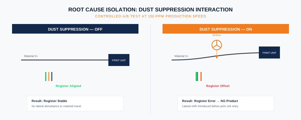
Figure 3 — Controlled A/B comparison isolating the dust suppression system as the source of lateral material shift at 150 PPM.
The investigation established a clear and repeatable correlation: with dust suppression OFF, printing register remained stable at 150 PPM; with dust suppression ON, material exhibited lateral shift prior to entering the printing unit, resulting in register error and non-conforming product.
This finding identified the root cause with precision: the dust suppression system, operating correctly within its own design intent, was introducing a lateral disturbance to material travel at high line speed — a dynamic interaction with no equivalent effect at 120 PPM, and no connection to the original flood damage or recovery work performed. The root cause was a process interaction, not a component failure — a materially different class of finding that required engineering reasoning, not component-level inspection, to identify.
Engineering Optimization
With the root cause identified, SRT implemented a targeted set of corrective actions:
Mechanical Alignment (Refinement). A further alignment pass was conducted on the material path leading into the printing unit, focused on minimizing sensitivity to lateral disturbance.
Dust Suppression Adjustment. Operating parameters — including airflow direction and intensity at the roller interface — were adjusted to reduce lateral force on the material web, while preserving the system's intended dust control function.
Guide Calibration. Side guide positioning and contact pressure were recalibrated to provide greater lateral restraint at the point material entered the printing unit.
Roller Parallelism. Parallelism between the dust suppression roller and downstream transport rollers was verified and corrected.
Final Production Validation. The production trial was repeated at full rated speed (150 PPM) with dust suppression active under normal operating conditions. Printing register accuracy and print quality were confirmed stable and within specification.
The engineering reasoning reflects a core principle: rather than disabling the dust suppression system to eliminate the symptom, SRT's approach addressed the underlying interaction — preserving full functionality of both printing performance and dust suppression simultaneously.
Project Results
- The machine was successfully returned to production, with mechanical, electrical, and control systems fully restored and verified.
- Register accuracy was validated as stable at full rated production speed (150 PPM), not merely at reduced test speed.
- Production consistency improved, with the identified process interaction resolved rather than masked or worked around.
- Process variability was reduced, as the root cause was engineered out of the system rather than managed operationally.
- Reliable operation was confirmed through a staged, production-representative commissioning process.
- Production performance was validated, closing the project on demonstrated capability rather than assumed readiness.
Equally significant is what did not happen: the machine was not returned with a hidden performance limitation, and the dust suppression system was not compromised or disabled to achieve a superficial resolution.
Engineering Lessons Learned
- Flood damage assessment must distinguish direct exposure from incidental proximity. Classification by verified condition, not location alone, determines the correct recovery scope.
- Commissioning must validate process capability, not just machine functionality. A machine that runs correctly is not the same as a machine that performs correctly under production conditions.
- Absence of a fault alarm does not mean absence of a problem. Performance issues can exist entirely outside a control system's fault-detection logic.
- Root cause analysis requires structured variable isolation, not general inspection. Systematically testing a suspected variable both active and inactive is often more effective than broad troubleshooting.
- Auxiliary systems can affect primary process performance in non-obvious ways. A subsystem not conventionally linked to a quality parameter should not be excluded from investigation.
- Speed-dependent phenomena require speed-representative testing. Validation at reduced or convenient test speeds may fail to reveal defects only present under full production load.
- Mechanical alignment is foundational but not always sufficient on its own. Additional refinement may be required once system-level interactions are understood.
- Engineering optimization should resolve root cause, not disable symptoms. Deactivating the dust suppression system would have resolved the register issue superficially while sacrificing an intended machine function.
- BURCE's traceability extends beyond recovery scope into commissioning findings. The same evidence-based discipline applied to damage assessment was applied to the root cause investigation.
ENGINEERING INSIGHT
The most valuable engineering finding in this project was not a damaged component — it was a hidden process interaction, surfaced only because commissioning was extended to full production-speed validation.
Had the project concluded once the machine demonstrated basic functionality, the register instability at rated speed would have remained undiscovered until it appeared during the client's own production operation — at a point where diagnosis is more disruptive, more costly in lost output, and less structured than during a controlled commissioning process.
This illustrates a broader principle in engineering recovery work: technical value is not created solely by restoring damaged components. It is created by validating that the restored asset performs as intended under real operating conditions, and by applying engineering reasoning to interactions that exist beyond the boundary of the original damage.
About BURCE
This project demonstrates the practical application of PT Sarana Rekayasa Tehnik's Bottom-Up Engineering Recovery Cost Estimation (BURCE) methodology across the full lifecycle of an asset recovery project — from component-level damage assessment, through mechanical and electrical restoration, to production-speed commissioning and root cause-driven engineering optimization.
BURCE develops Recovery Cost Estimation from the component level upward, ensuring that every engineering recommendation — whether a repair decision made during assessment or a corrective action identified during commissioning — is technically justified, fully traceable to supporting evidence, and ultimately validated through demonstrated production performance rather than assumed readiness.
Facing a flood, fire, or mechanical damage scenario on production-critical equipment? Contact the SRT engineering team for an independent technical assessment.
Related reading: Flood-Damaged Electric Motor Recovery (Engineering Handbook) →